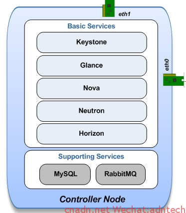
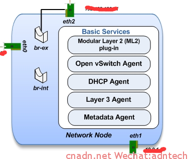
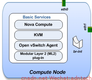
在三台vmware的虚拟机上模拟安装三节点openstack,网络设计如下,该结构在控制节点上安装nova,glance,keystone,neutron, horizon, 在network节点上安装网络服务相关的各种plugin,计算节点上安装nova计算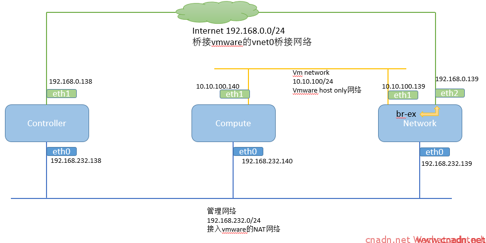
在上述网络中,compute的 eth1 和 network的eth1 通过GRE tunnel构成二层互联,DHCP服务运行在network节点上,当一个vm在compute上启动后,dhcp服务可以通过GRE隧道给该vm自动分配IP。
在network节点上, eth2与br-ex接口同时连接在br-ex这个桥上,br-ex接口分配192.168.0.139的IP,eth2设置为混杂模式。当openstack配置external网络后,external网络接口被连接到br-ex桥上:
|
1 2 3 4 5 6 7 8 9 10 11 12 |
Bridge br-ex Port "eth2" Interface "eth2" Port veth-ex Interface veth-ex type: internal Port br-ex Interface br-ex type: internal Port "qg-6f726a6c-41" Interface "qg-6f726a6c-41" type: internal |
条件准备:
1. ubuntu 14.04 64位版本
root@controller:/home/mycisco# lsb_release -a
No LSB modules are available.
Distributor ID: Ubuntu
Description: Ubuntu 14.04.1 LTS
Release: 14.04
Codename: trusty
分别安装三台vm,安装时候只安装openssh服务,不要安装任何其他服务,保证vm能够连接互联网,我是利用上述的管理员位于vmware workstation网络的NAT网络中,因此可以通过管理口上网更新安装包
2.各台机器的安装按照下面这个文档进行:
https://github.com/ChaimaGhribi/OpenStack-Icehouse-Installation/blob/3d9581f92919fedbd984105cb24be623a40c56ec/OpenStack-Icehouse-Installation.rst
整个过程可以完全step by step这个文档,只是需要将相关IP或者hostname替换为自己的,我没有使用hostname,所以所有配置文件中都是配的IP
==========
各节点安装的服务内容
==========
控制节点:
apt-get install -y nova-api nova-cert nova-conductor nova-consoleauth nova-novncproxy nova-scheduler python-novaclient
neutron
apt-get install -y neutron-server neutron-plugin-ml2
网络节点:
apt-get install -y vlan bridge-utils
apt-get install -y neutron-plugin-ml2 neutron-plugin-openvswitch-agent dnsmasq neutron-l3-agent neutron-dhcp-agent
计算节点:
apt-get install -y kvm libvirt-bin pm-utils
apt-get install -y nova-compute-kvm python-guestfs
apt-get install -y neutron-common neutron-plugin-ml2 neutron-plugin-openvswitch-agent
Openstack 网络理解:
一个虚机的数据外出的路径path:
1 计算节点上执行 /var/lib/nova/instances/***instaneID***/libvirtu.xml中找到:
<source bridge="qbrfe14f930-df"/>
<target dev="tapfe14f930-df"/>
source bridge是 ifconfig输出里的qbr开头的接口,这个bridge负责vm和linux host系统之间的桥接. tap即表示该vm上的自身的虚拟接口。
2. 查找qbr对应桥包含哪些port,计算节点上执行 brctl show:
|
1 2 3 4 5 6 7 8 |
root@compute:/home/mycisco# brctl show bridge name bridge id STP enabled interfaces qbr01f68373-1a 8000.a2973af9e29b no qvb01f68373-1a qbr02cbe170-46 8000.928b3817502b no qvb02cbe170-46 qbrd1b64bc7-d8 8000.aec37b36f441 no qvbd1b64bc7-d8 qbrfe14f930-df 8000.c69b1321712b no qvbfe14f930-df tapfe14f930-df virbr0 8000.000000000000 yes |
可以看到qbrfe14f930-df 上连接了两个端口,一个是tapfe14f930-df一个是qvb开头的接口,tap是vm自己接口, qvb是 oopenvswitch中br-int这个桥的一个接口,这样vm的接口
就和ovs连接起来。
3. 查看ovs中各个接口情况,计算节点上执行 ovs-vsctl show
|
1 2 3 4 5 6 7 8 9 10 11 12 13 14 15 16 17 18 19 20 21 22 23 24 25 26 27 28 29 30 31 32 33 34 35 36 |
root@compute:/home/mycisco# ovs-vsctl show b5553502-95e4-4ad2-90a6-a3da02d3819d Bridge br-tun Port "gre-0a0a648b" Interface "gre-0a0a648b" type: gre options: {in_key=flow, local_ip="10.10.100.140", out_key=flow, remote_ip="10.10.100.139"} Port br-tun Interface br-tun type: internal Port patch-int Interface patch-int type: patch options: {peer=patch-tun} Bridge br-int fail_mode: secure Port br-int Interface br-int type: internal Port "qvo02cbe170-46" tag: 2 Interface "qvo02cbe170-46" Port "qvod1b64bc7-d8" tag: 1 Interface "qvod1b64bc7-d8" Port patch-tun Interface patch-tun type: patch options: {peer=patch-int} Port "qvo01f68373-1a" tag: 3 Interface "qvo01f68373-1a" Port "qvofe14f930-df"《《《《《《《《《《《《《《《《《《《《《《《《 tag: 2 Interface "qvofe14f930-df" ovs_version: "2.0.2" |
qvofe14f930-df这个接口其实就对应于qvbfe14f930-df。
4. 然后只要 br-int这个桥中有一个接口和另一个包含有实际linux host物理口的桥对接上,本例实际是物理接口形成的GRE 隧道
所以针对上述实验网络数据去公网或者两个tenant之间的数据路由path逻辑就是:
compute节点的vm interface(tap***)---qbr****-qvb****(br-int桥里的qvo****)---gre tunnel(br-int桥里的tunnel 端口)----br-tunnel 桥(tunnel通道)----network节点br-tunnel--network节点的br-int----路由器接口.....
下面这张图清晰描述了一个compute主机内vm是如何和provide网络通信的(vlan tagged 网络类型):

-------------------------------------------------------------
网络节点上ovs-vsctl show输出意义
qr-****表示路由器接口
tap***一般会代表一个设备接口,例如代表dhcp服务器接口,注意根据ID和GUI上各个设备或者网络的ID来对应
brctl show在 计算节点上输出linux的 bridge
ovs-vsctl show 在网络节点上输出ovs的bridge
ip netns list 网络节点上输出namespace
----------------------------------------
------
如何查看openstack中虚拟路由器的内部路由,接口情况,或模拟路由器上执行命令:
1. ip netns show 获得路由器的namespace
|
1 2 3 4 |
root@network:/home/mycisco# ip netns show qdhcp-70f7aa46-b66b-455e-896e-05f94a08fcb8 qrouter-040c1455-6096-4806-ba91-fec64cdaed81 <<<<<<<<<<< qdhcp-4e3f621f-d6b9-4438-be58-aa51d3c2e061 |
2. 在namespace的上下文中执行名利即可
|
1 2 3 4 |
ip netns exec qrouter-040c1455-6096-4806-ba91-fec64cdaed81 ip route ip netns exec qrouter-040c1455-6096-4806-ba91-fec64cdaed81 ifconfig ip netns exec qrouter-040c1455-6096-4806-ba91-fec64cdaed81 ping 。。。 ip netns exec qrouter-040c1455-6096-4806-ba91-fec64cdaed81 iptables-save |
-------------------------------------------
在openstack的GUI上配public 网络的步骤
1. admin--network 下配置一个网络,该子网的网段填写和物理机对外连接网络相同IP, 网关填写外部网络的真实网关
2. project-routers 直接点击set router gateway 并选择对应的public网络。 此步操作后,网络节点上,系统将自动在bri-ex桥中加入一个qg-****这样的接口,这个qg接口就是GUI界面上external网络的路由器接口。
注:如果想在ubuntu 12版本上安装havana的话,可以参考
http://www.revolutionlabs.net/2013/11/part-1-how-to-install-openstack-havana.html
我曾按照这个在14.04上安装,出现各种问题,虽然最后google解决,并安装出来,horizon上操作时候总是会报未授权错误,虽然操作还能继续。。